Hi !
So I took lots of notes about updating Arduinos when in Boston…but 6 weeks later, I am not 100% confident !
Would be great to have a detailed guide for that…
Thanks !
Damien
Hi !
So I took lots of notes about updating Arduinos when in Boston…but 6 weeks later, I am not 100% confident !
Would be great to have a detailed guide for that…
Thanks !
Damien
Great question. I’ve been meaning to do this so here is it:
Note: All this information is reposted from Sparkfun’s website (SAMD21 Mini/Dev Breakout Hookup Guide - SparkFun Learn)
Their website should be pretty straight forward to navigate around.
The Sparkfun website has a very good blog on this. For any more details, please refer to that link. I am just copying details from their blog over here.
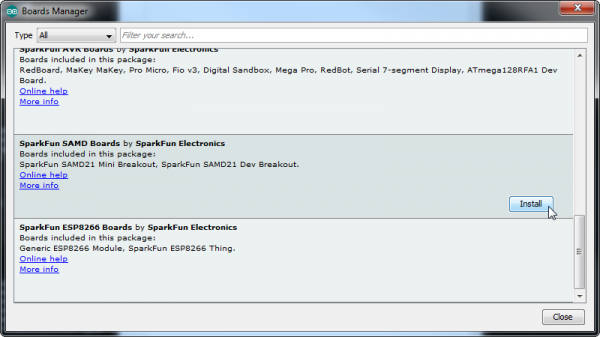
Navigate to your board manager ( Tools > Board > Boards Manager… ), then find an entry for Arduino SAMD Boards (32-bits ARM Cortex-M0+) . Select it, and install the latest version
First, open your Arduino preferences ( File > Preferences ). Then find the Additional Board Manager URLs text box, and paste the below link in:
https://raw.githubusercontent.com/sparkfun/Arduino_Boards/master/IDE_Board_Manager/package_sparkfun_index.json
Then hit “OK”, and travel back to the Board Manager menu. You should (but probably won’t) be able to find a new entry for SparkFun SAMD Boards . If you don’t see it, close the board manager and open it again.
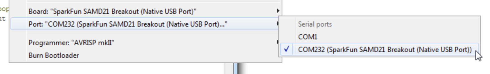
The boards used in eVOLVER are the SAMD21 Mini boards. The port changes based on which USB the Arduino is connected to. The wrong port is typically the most common reason why the Arduino won’t upload.
Choosing the board:
Choosing the port:
The scripts can be found on our Github Page. After downloading the scripts, please copy the libraries folder into your local Arduino libraries folder. For example, on my computer, it is under Documents > Arduino > libraries
Copy these files into your local Arduino libraries folder.
This should be all. Open up the files and upload your scripts to the microcontroller via microUSB! A quick tip: there are many poorly designed microUSB cables out there (e.g. just for charging). Be careful to use one that you know works. If you can’t upload, try another cable.
Excellent, thank you ! Just one last question…there are 4 arduinos in our machine (stir, Temp, OD90 and OD135) as well as at least one in the fluidic box. So when we download a new release from the Fynch Github for the Arduinos, I guess we have to connect with the microUSB and update them one by one ? Including the one(s) in the fluidic box ?
Thanks !
Damien
Yep that’s correct! We are working on getting automatic updates from the Raspberry Pi up and running. But no bandwidth to do so…
Brandon
Hello, I was hoping to update our eVOLVER with the most recent software update, and was wondering if I need to expose the PWM boards inside the tray in order to update the code, as I don’t see any microUSB ports on the outside of the eVOLVER, or if there has been changes to how Arduino updates are handled
There are two 4-40 screws in the front of the eVOLVER. If you unscrew those, you should be able to lift the lid and have access to the Arduinos.
I’ve been struggling with getting data through the arduinos. After reuploading code onto them I get the green TX indicator light on all but the fluidics arduino.
I wasn’t getting consistent TX indicators before and wondering what’s going on with it. Is that just an indicator that they share a serial line on the mother board? Should the fluidics arduino be giving me a TX light?
Thanks!
Ben
Can you elaborate more, by data you mean you are trying to upload the Arduino sketches or are you trying to communicate from the Pi to the Arduino. Is this TX indicator on the Arduino or some RS485 communication shield that you are using?
Sometimes, if it is in fact the Arduino, holding down the reset button or double tapping it can help it
https://learn.sparkfun.com/tutorials/samd21-minidev-breakout-hookup-guide/troubleshooting
The specific issue is with uploading the sketches to each microcontroller. Once the code is on the arduino the TX indicator will flash green until I remove the microUSB, then go solid green. Sometimes it takes a few tries to get it into that state, but for the motherboard all 3 arduinos are green. The arduino on the fluidics board however does not give a green TX indicator. I tried uploading other sketches to the fluidics arduino and loading the fluidics code to a different arduino but neither results in a green TX indicator. Just from doing tutorials, I thought that light meant the code is loaded and the arduino can do it’s job.
The larger issue I am having is that I am not getting any indication that data is going through the arduinos. I’m getting pulses of data every 30sec from the RPI that I can trace with an oscilloscope all the way to the input pins of the arduinos, but I can’t issue control signals via the GUI. I also get voltage changes from the vial boards back to their proper pins, but I don’t get any readings from running the calibrations.
Now that I’m writing this, I realize the boards are the original designs from your paper, but I uploaded the most current arduino files. That could be part of the problem.
I have found the green light to be inconsistent with if the code is properly uploaded or not. So I wouldn’t read too much into it.
I have a few points and questions:
Brandon
The green indicator is serial as you suspected, and I have likewise found it to be somewhat inconsistent; however, when you upload code, the yellow-orange RX LED on the other side of the chip should flash in a specific pattern before the blue power light next to the MicroUSB port comes back on.
If you haven’t tried already, Brandon had previously suggested changing serialEvent (line 196 of RS485_FLUIDICS) to the code below and submitting the commands via USB through the Arduino serial monitor. The fluidics is more confusing than some of the other parameters, but you should be able to just copy and paste in the examples at the top of the sketch into the Arduino Serial Monitor and see if you can control the pumps.
Thanks for these clarifications!
Our layout is the same as presented in the supplementary section of the paper and we are using the abelectronics RS485 shield you recommended. I can follow the chirps of data that come from an active eVOLVER GUI all the way to the arduinos, so I’m confident data is getting out. I see your point though that it doesn’t mean I can control anything. I’ve attached the layout below.
I was hoping it wouldn’t come to writing debug scripts, but I guess I signed up for it.
Ben
@BBBartelle Another thing to try is pressing the reset button on the arduino twice. The led should turn amber. Then try uploading the code again. I have found that sometimes the arduinos get into a weird state where they don’t upload code properly and this sometimes solves the issue.